Subsystem C
Hardware Design Project for ECE295
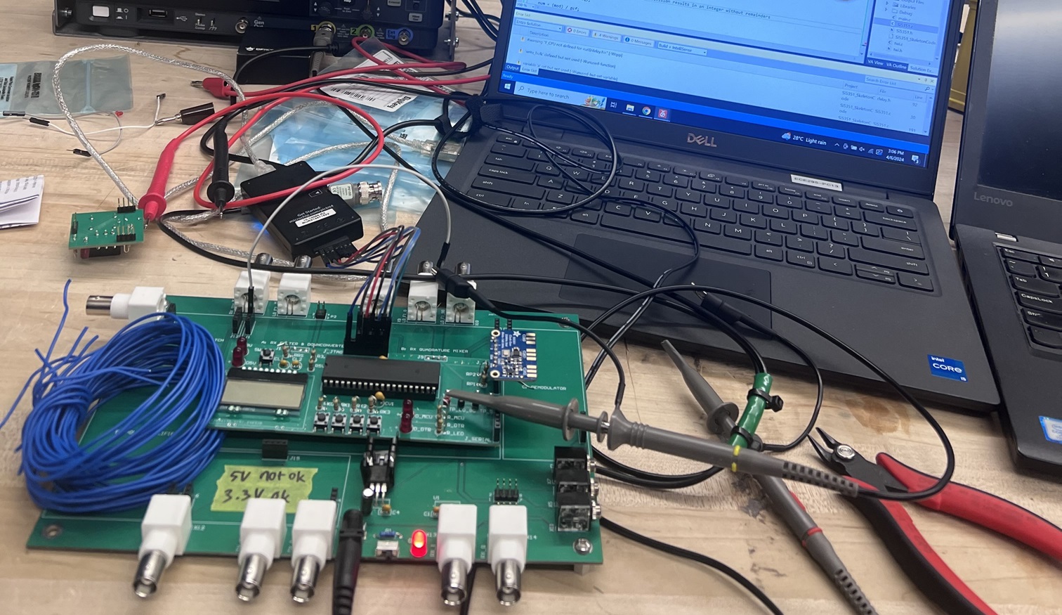
Testing firmware for local oscillator: Checking if frequencies can be manually updated by ∓ 1kHz
Subsystem Overview
Subsystem C consists of two submodules: (1) the Microcontroller unit (MCU) and Local Oscillator (LO), and (2) the Transmit/Receive (TX/RX) switch. They serve to generate frequencies for the software-defined radio (SDR), and to toggle between TX/RX modes. The generated LO signals are used by the quadrature mixers of Subsystems A and D to downconvert received signals to an intermediate frequency so that it can be processed by later subsystems (RX) or upconvert outgoing signals to be transmitted from the SDR antenna (TX). The TX/RX switch controls the activation of specific subsystems based on the current state of the radio. This subsystem is controllable with a user interface (UI) or a PC via USB, and will include a display as part of the UI.
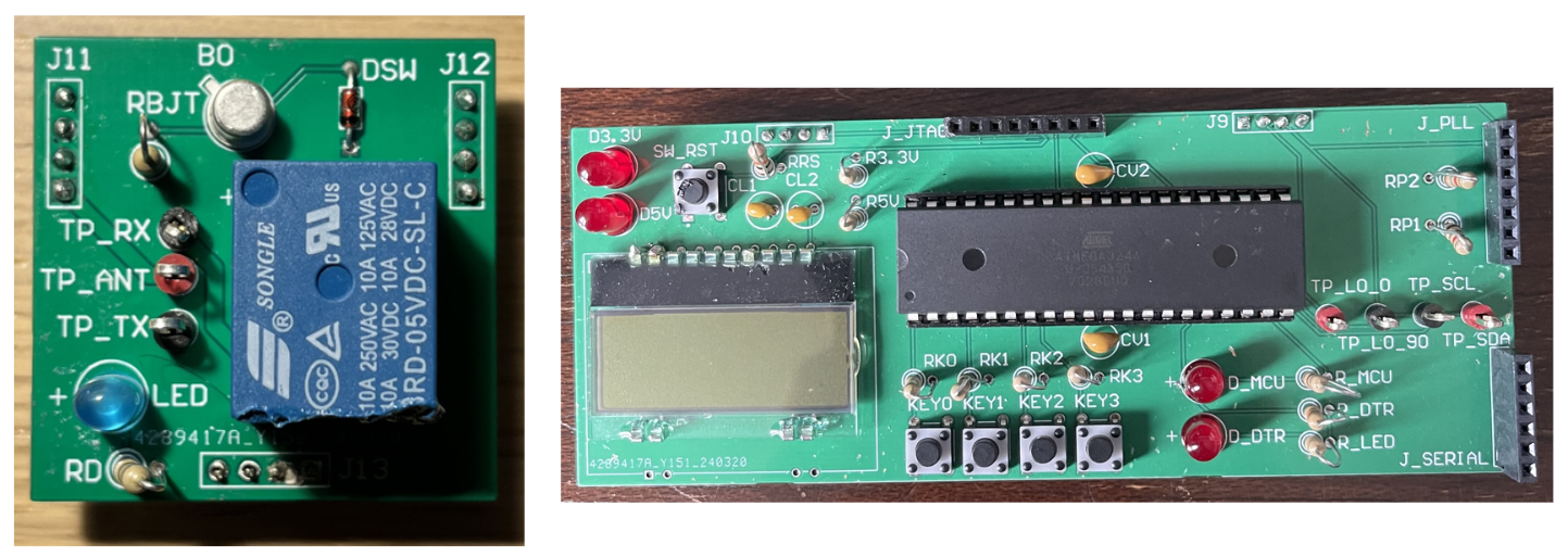
Assembled boards: RX/TX switch (left) and LO and MCU (right).
Design Timeline
The team began the design from the conceptual level. High level block diagrams were visualized to begin understanding how each part of the subsystem should come together and work with the rest of the radio. The first design review involved an Altium schematic of port connections and component selections. Components were selected with simplicity and practicality in mind. There were three requirements the system must meet including tuning the radio by ∓ 1kHz, generating frequencies in the MHz range and controlling the radio with UART (computer) commands. Design review 2 involved the finalized PCB layout with parts, traces and verifications completed. This was followed by sending out the design for manufactering, then soldering everything together for the final design review: unit testing.
To learn more
Check out the presentation deck below.